Normal maps are essential for adding surface detail to 3D models without increasing polygon count.
Understanding which normal map format to use depends on your target rendering engine, workflow requirements, and the specific 3D software in your pipeline. This comprehensive guide will walk you through the technical differences, implementation steps, and best practices for selecting the right normal map format for your 2026 projects.
Understanding the Technical Difference Between OpenGL and DirectX Normal Maps
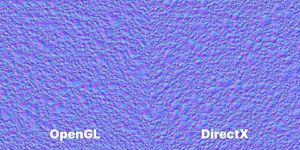
The primary distinction between OpenGL and DirectX normal maps lies in how they interpret the Y-axis (green channel) information. DirectX normal maps use a Y-up coordinate system where positive Y values point upward, while OpenGL normal maps use a Y-down system where positive Y values point downward. This fundamental difference affects how surface bumps and indentations appear when rendered.
In practical terms, if you apply a DirectX normal map in an OpenGL-based renderer without conversion, all the surface details will appear inverted – bumps become dents and raised areas appear recessed. The X (red) and Z (blue) channels remain consistent between both formats, making the conversion process straightforward but critical for accurate results.
Most modern 3D software packages and game engines handle this conversion automatically, but understanding the underlying mechanics helps prevent rendering issues when working across different platforms. Blender, for example, uses OpenGL convention internally, while Unreal Engine follows DirectX standards, requiring careful attention when transferring assets between these environments.
Step-by-Step Process for Converting Between Normal Map Formats
Converting between OpenGL and DirectX normal maps requires inverting the green channel values. Here’s the detailed process for multiple software packages:
1: Photoshop Conversion
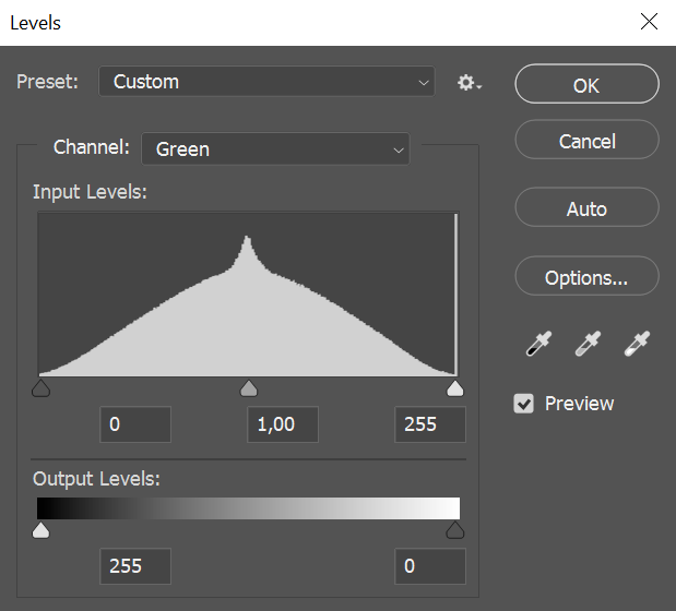
- Open your normal map in Adobe Photoshop
- Navigate to the Channels panel and select the Green channel
- Press Ctrl+I (Windows) or Cmd+I (Mac) to invert the channel
- Return to the RGB composite view to see the converted normal map
- Save your file with a clear naming convention (e.g., “_DirectX” or “_OpenGL” suffix)
2: Blender Shader Editor Approach
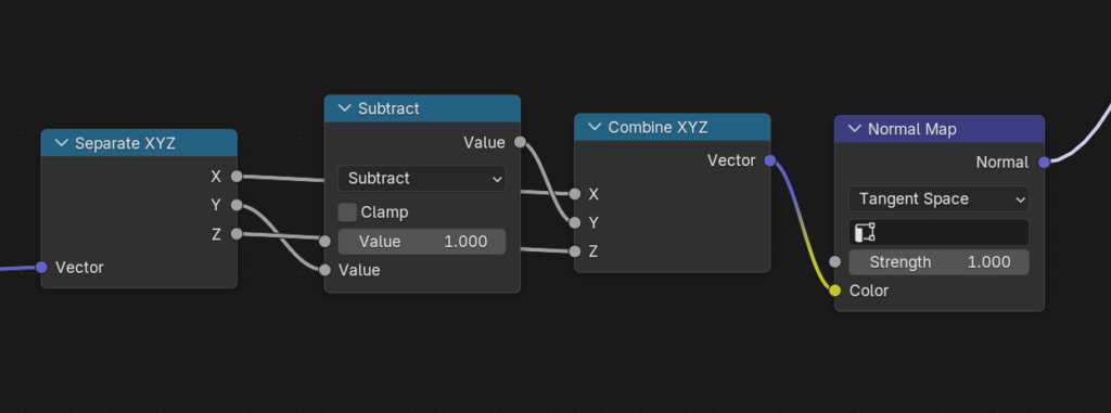
- Load your material in Blender’s Shader Editor
- Add a Separate RGB node between your Image Texture and Normal Map nodes
- Connect the Green output to a Math node set to “Subtract”
- Set the second input value of the Math node to 1.000
- Add a Combine RGB node and reconnect all channels, using the Math node output for Green
- Connect the Combine RGB output to your Normal Map node
3: Substance Designer Conversion
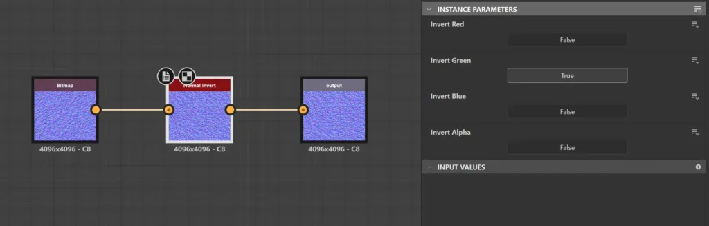
- Create a new Substance Designer graph
- Add your normal map as an input bitmap
- Insert a Normal Invert node
- In the Normal Invert Instance Parameters, invert the Green channel by pressing ‘True’ below the ‘Invert Green’
- Export the result with appropriate naming conventions
Complete List of Software Where to Use Normal Map OpenGL or DirectX
| Software / Renderer | Normal Map Standard |
| Unreal Engine (4 & 5) | DirectX (-Y) |
| Unity | OpenGL (+Y) |
| Blender (Cycles / Eevee) | OpenGL (+Y) |
| Autodesk Maya | OpenGL (+Y) |
| Autodesk 3ds Max | DirectX (-Y) |
| Substance Painter | Selectable (Both) |
| Marmoset Toolbag | Selectable (Both) |
| ZBrush | OpenGL (+Y) |
| Cinema 4D | OpenGL (+Y) |
| Houdini | OpenGL (+Y) |
| Godot Engine | OpenGL (+Y) |
| CryEngine | DirectX (-Y) |
| Arnold Renderer | OpenGL (+Y) |
| V-Ray | OpenGL (+Y) |
| Corona Renderer | OpenGL (+Y) |
| OctaneRender | OpenGL (+Y) |
| Redshift | OpenGL (+Y) |
| Source Engine 2 | DirectX (-Y) |
| KeyShot | OpenGL (+Y) |
| ArmorPaint | OpenGL (+Y) |
| XNormal | OpenGL (+Y) |
| Sketchfab Viewer | OpenGL (+Y) |
| O3DE (Open 3D Engine) | DirectX (-Y) |
Software-Specific Implementation Guidelines
Different 3D applications handle normal map formats with varying degrees of automation. Understanding these nuances ensures consistent results across your pipeline.
Blender Implementation
Blender uses OpenGL convention by default. When importing normal maps, enable the “Non-Color” color space for your normal map textures and check the shader setup carefully. The Normal Map node includes a “Non-Color” input that should always be used for normal map textures to prevent gamma correction issues.
Unreal Engine Configuration
Unreal Engine 5 automatically handles normal map interpretation through its texture import settings. When importing textures, set the Texture Group to “WorldNormalMap” and enable “Flip Green Channel” if your source uses OpenGL convention. The engine’s material editor provides visual feedback for incorrect normal map orientation, making troubleshooting straightforward.
For architectural visualization and real-time rendering, Unreal Engine’s virtual texturing system works exceptionally well with high-resolution normal maps up to 8K resolution, providing excellent detail streaming for complex scenes.
Common Pitfalls and Troubleshooting Solutions
Several technical issues commonly arise when working with normal maps across different software packages and rendering engines.
Tangent Space Mismatches
Beyond the OpenGL/DirectX format difference, tangent space calculation methods can vary between applications. Maya uses different tangent space calculations than Blender, which can cause subtle but noticeable differences in normal map appearance. When transferring assets between software packages, always test render a simple sphere with your normal maps to verify surface detail orientation.
Texture Compression Artifacts
GPU texture compression algorithms can introduce artifacts in normal maps, particularly affecting the critical green channel information. When targeting real-time applications, test your normal maps with BC5 compression (for DirectX) or similar formats to ensure detail preservation. Avoid DXT1 compression for normal maps as it doesn’t provide sufficient precision for the green channel.
Color Space and Gamma Issues
Normal maps must always use linear color space, never sRGB gamma correction. This technical requirement affects how the RGB values are interpreted by the shader system. Always set normal map textures to “Non-Color” or “Raw” color space in your 3D application to prevent gamma-related artifacts that can make surfaces appear overly bumpy or flat.
Conclusion
Selecting the appropriate normal map format directly impacts the visual quality and technical accuracy of your 3D renders. Whether you’re creating architectural visualizations, game assets, or product renderings, understanding these format differences ensures professional results across all target platforms. The conversion process, while technically straightforward, requires attention to detail and proper implementation within your specific software pipeline.
For 3D artists working with diverse software packages and rendering engines, having access to high-quality PBR materials that include properly formatted normal maps streamlines the entire process. CGAxis All-Access subscription provides over 12,600 production-ready assets with normal maps available in both OpenGL and DirectX formats, ensuring compatibility across your entire workflow regardless of your target platform or rendering engine.


